


THE LEAD LADS® / PROJECT ARCHIVE
Specialist Code 5 lead coverings to the railway footbridge at Selby Station, incorporating stepped bays, timber core rolls, apex cappings, complex stair-tower interfaces and bespoke lead details over a new steel and timber supporting structure.
SELBY · NORTH YORKSHIRE · RAIL INFRASTRUCTURE · SPECIALIST LEAD ROOFING
Explore the Project01 — THE PROJECT
The Lead Lads® completed the specialist lead sheet coverings to the pedestrian footbridge at Selby Train Station in North Yorkshire.
Unlike a conventional roof, the bridge combines long sloping elevations, changes in level, stepped stair sections, core-roll joints, ridge geometry and numerous interfaces where separate parts of the structure meet.
Following renewal of the structural framework and timber supporting surfaces by the principal contractor, our work concentrated on setting out, forming and installing the Code 5 lead coverings across the bridge.
LOCATION
PROGRAMME
LEAD CODE
SECTOR
02 — THE GEOMETRY
The footbridge does not present a single uninterrupted roofing plane.
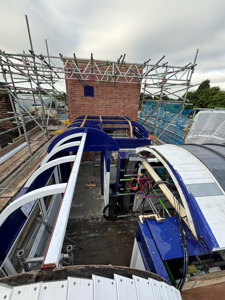
Its geometry changes through the bridge span and into the stair towers, creating different slopes, stepped sections, changes in height and multiple intersecting details.
Each lead bay therefore had to be understood in relation to the structure around it rather than repeated as a standard roofing module.
The long bridge elevations could be set out in a comparatively regular sequence, while the stair sections required more individual pieces and substantially more interface detailing.
03 — THE LEADWORK
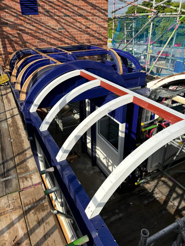
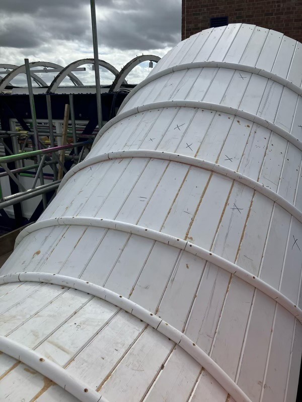
The principal contractor installed the supporting timber substrate and wood core rolls to the agreed setting-out dimensions.
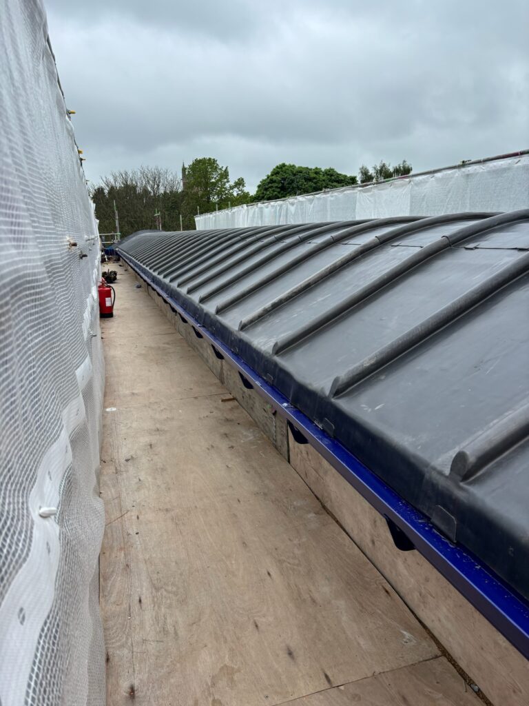
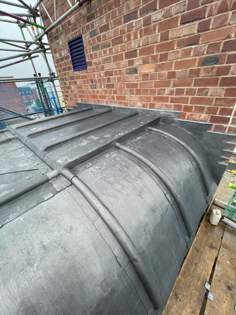
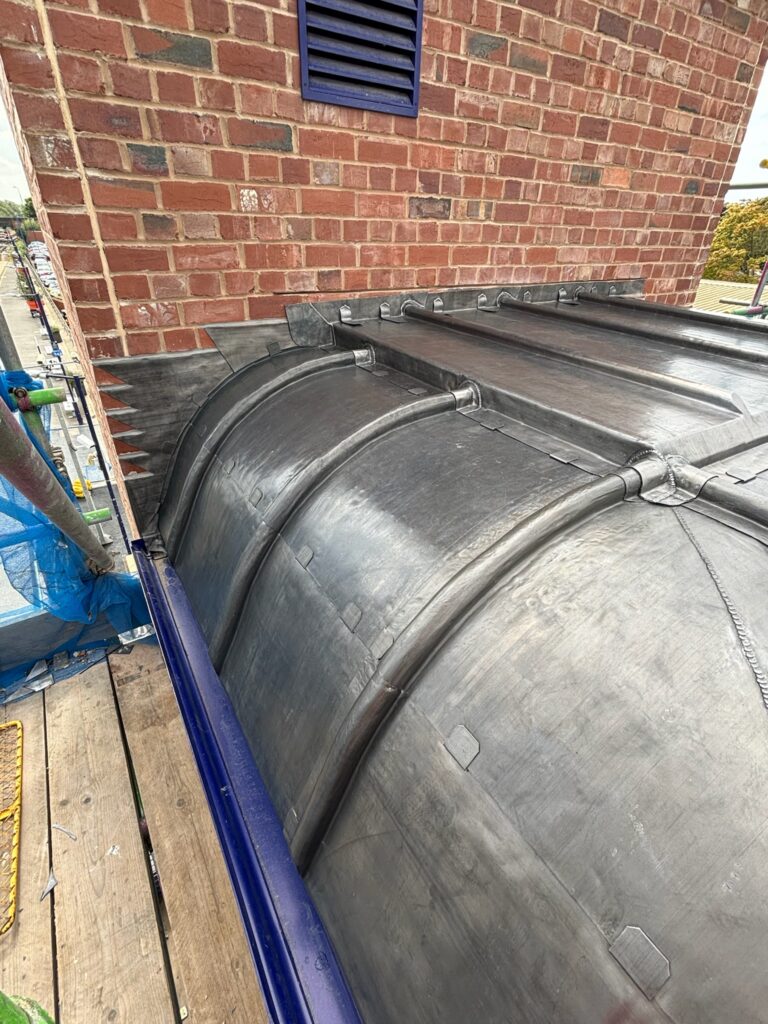
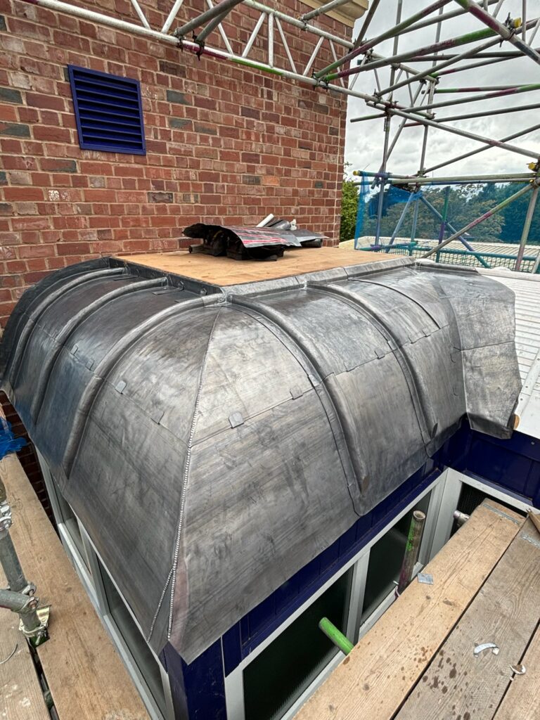
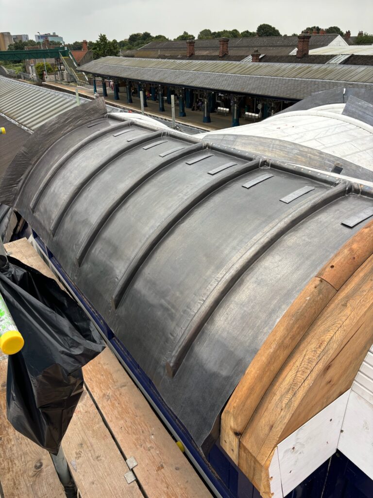
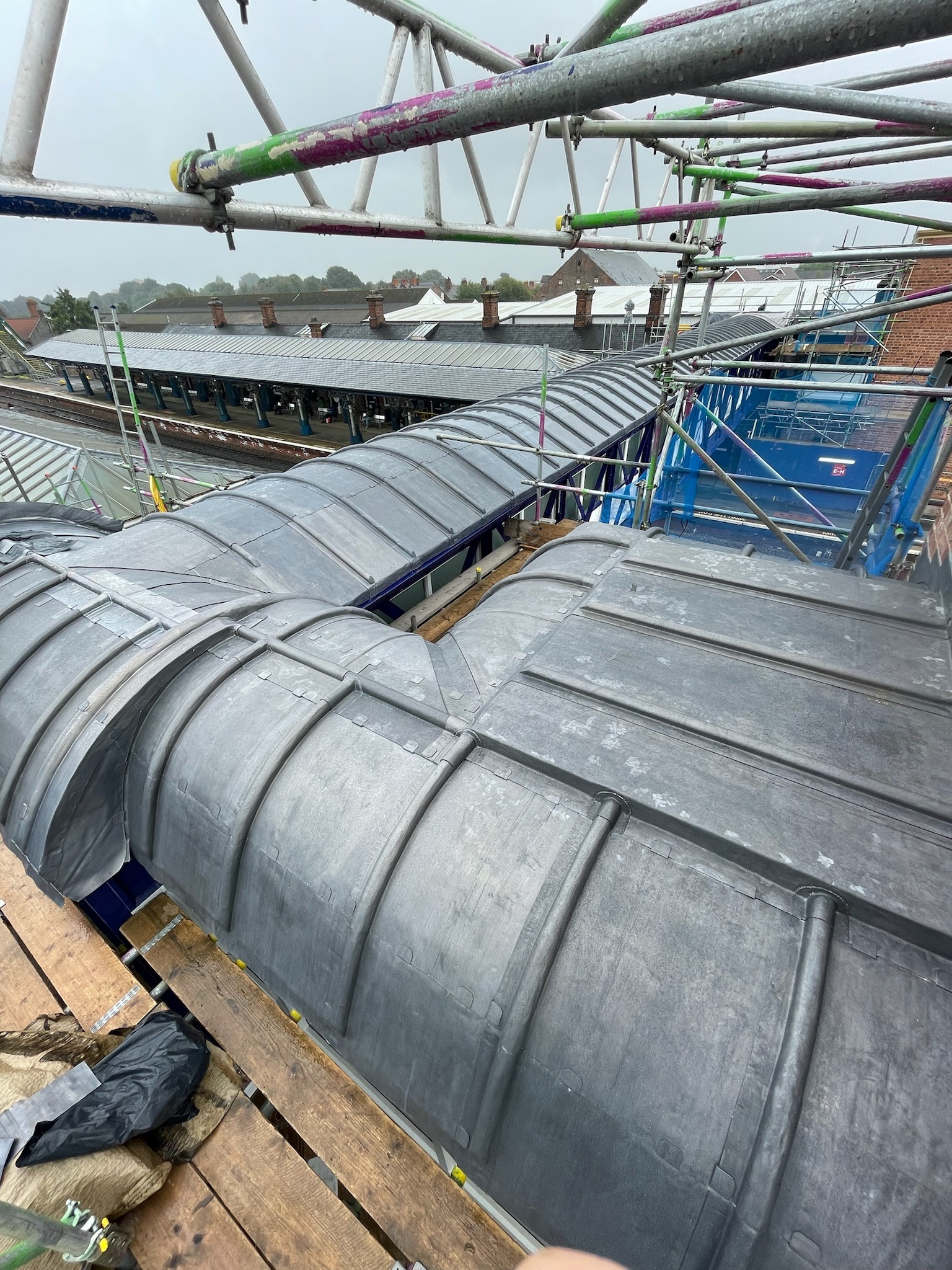
Our leadwork then progressed elevation by elevation, with individual sheets formed around those rolls to create the principal weathering bays.
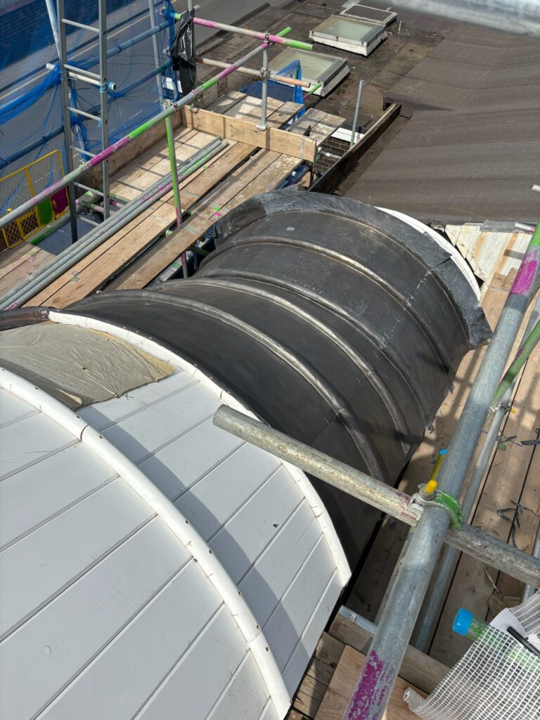
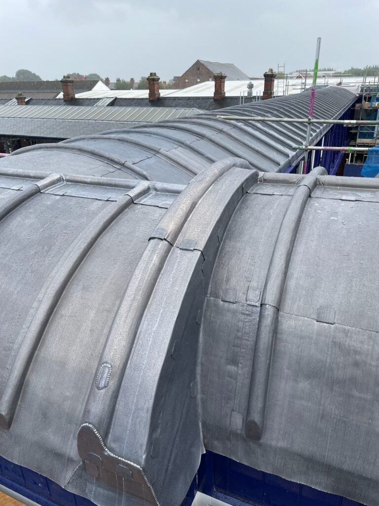
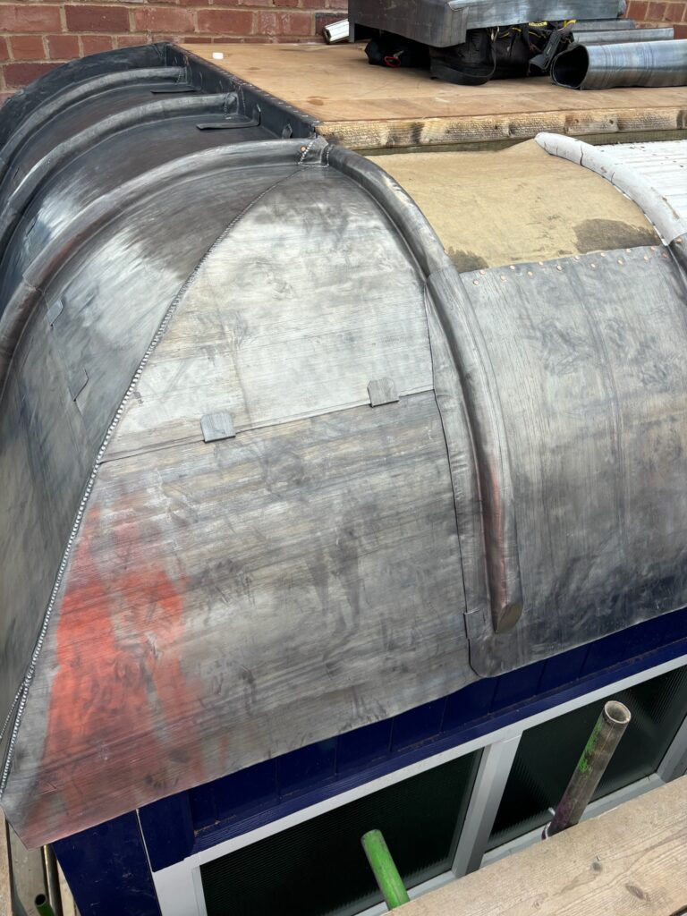
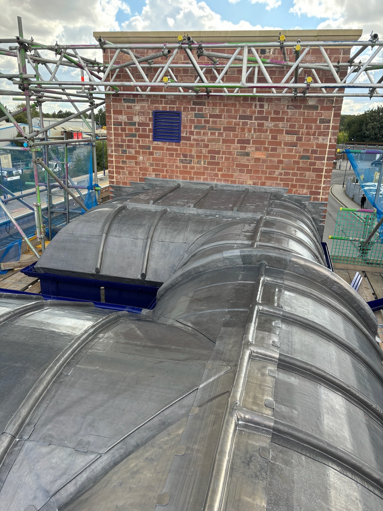
At the upper junction, the opposing bridge slopes were resolved through a separately formed apex capping. Lead tabs, laps and the interfaces between the capping and roll details had to maintain continuity while still accommodating normal sheet movement.
The result is a large-scale covering assembled from individually considered sections rather than one continuous skin.
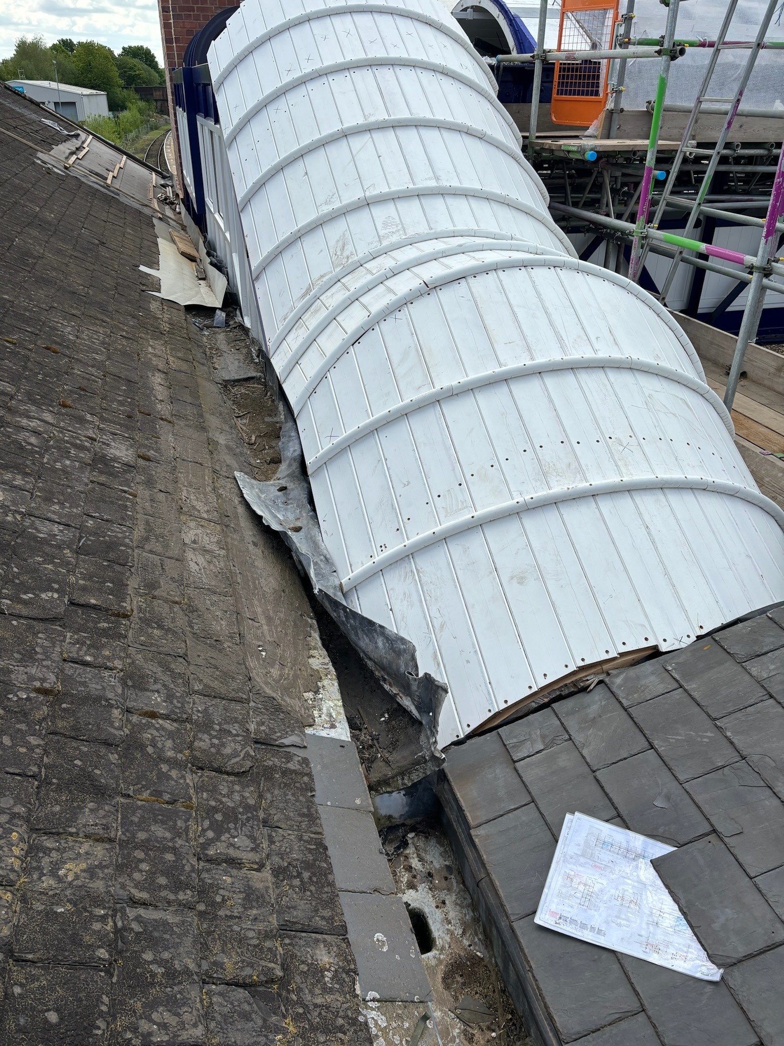
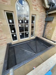
The bridge structure before installation of the new specialist lead coverings.

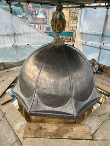
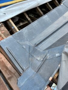
Individual lead sections formed around the bridge geometry and timber roll arrangement.

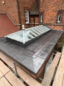
The finished lead covering forming one continuous weathering system across the footbridge.
04 — STEEL + TIMBER
The finished leadwork is only the external weathering layer of a much larger construction.
Beneath it sits the renewed steel bridge framework and supporting timber substrate installed by the principal contractor.
The accuracy of the substrate and core-roll arrangement directly influences the finished leadwork. Rolls establish sheet divisions and joint positions, while the supporting surface provides the geometry against which the lead is dressed.
Close coordination between structural, carpentry and leadwork packages was therefore essential before installation progressed.
05 — MOVEMENT + RESTRAINT
A structure of this scale exposes substantial areas of sheet lead to changing temperatures and weather conditions.
The coverings were therefore divided into individual sections with laps, rolls, tabs and compatible clips used as part of the overall movement strategy.
Copper and stainless-steel clips were incorporated where appropriate to restrain vulnerable edges and sections without unnecessarily preventing normal thermal movement.
06 — SIGNATURE DETAIL
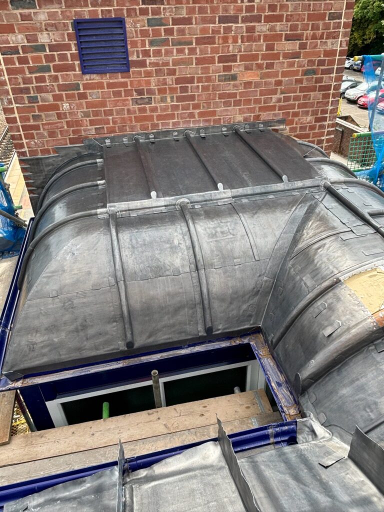
The most technically demanding areas occurred where the regular bridge elevations transitioned into the stair structures.
Here the leadwork had to negotiate changes in height, direction and supporting geometry while maintaining continuity with the adjoining bays.
Standard repeated pieces gave way to bespoke sections, local flashings, dressed interfaces and carefully resolved overlaps.
This is where the project becomes less about laying sheets and more about interpreting a three-dimensional structure in lead.
07 — COORDINATION + SUPPORT
08 — LEADWORK INSTALLATION
09 — MATERIALS
10 — THE CRAFT
The project combines traditional hand skills with the coordination required for a large engineered structure.
11 — PROJECT RECORD
The Selby project record captures considerably more than a finished lead roof.
It shows the progression from the underlying bridge construction through the individual leadwork operations to the completed covering — useful evidence of the amount of hidden work behind the final appearance.
12 — RAIL INFRASTRUCTURE
Selby Station opened in the nineteenth century and remains part of an active railway network.
The footbridge project therefore combined traditional sheet-lead workmanship with the practical constraints associated with working on transport infrastructure.
Access, sequencing, interfaces with other trades and protection of completed work all became part of the delivery process.
This is an important distinction: specialist leadwork at this scale depends as much on coordination and planning as it does on the final hand-formed details.
13 — TECHNICAL KNOWLEDGE
BS 6915 — Proper Leadwork →
BS EN 12588 — Rolled Lead Sheet →
LSTA Guidelines →
Leadwork Standards Hub →
The Lead Handbook →
Lead Roofing Guides →
These pages connect the finished project to the material specification, installation principles and practical detailing behind it.
14 — WHAT THIS PROJECT SHOWS
The Selby footbridge demonstrates the adaptability of sheet lead.
The same underlying principles used on a bay roof or lead gutter — support, sheet dimensions, movement, laps, rolls and compatible restraint — can also be applied to a much larger and more geometrically complex structure.
What changes is the scale, coordination and number of interfaces involved.
Rather than simplifying the craft, a project of this size magnifies the importance of correct setting out and disciplined detailing.
PROJECT TAKEAWAYS
15 — FREQUENTLY ASKED
Sheet lead can form durable weathering over complex shapes and can be divided into individual sections around curves, slopes, rolls and structural junctions.
Code 5 rolled lead sheet was used for the bridge coverings on this project. Lead selection for another structure should reflect the particular sheet dimensions, geometry, support and specification.
Core rolls create raised joints between adjacent sections of lead and help divide a larger covering into individual bays while forming a traditional weathering detail.
They introduce changes in direction, height and slope, meaning fewer details can simply be repeated. Individual sheets and flashings have to be formed around the actual geometry.
Compatible clips can help restrain edges and sections of sheet while still allowing the lead to respond to normal thermal movement.
16 — MATERIALS + RESOURCES
Lead Roofing Project Archive →
Featured Leadwork Projects →
Lead Roofing →
Heritage Leadwork →
Leadwork Sectors →
Code 5 Rolled Lead →
Wood Core Roll →
Lead Underlay →
Leadwork Fixings →
THE LEAD LADS® / PROJECT ARCHIVE
Selby Station Footbridge forms part of The Lead Lads® project archive documenting specialist lead roofing across traditional buildings, infrastructure, historic structures and complex architectural details.
From repetitive bridge bays to bespoke stair-tower interfaces, the project demonstrates how traditional sheet-lead principles can be applied at infrastructure scale without losing the precision of individual craftsmanship.